Sponsored
I'm building a fully-integrated digital source solution for Acura Integra ELS / Honda Civic Bose (new thread title)
bicycle_wreck
New Member
- Joined
- Mar 7, 2026
- Threads
- 0
- Messages
- 3
- Reaction score
- 4
- Location
- Knoxville, TN
- Car(s)
- 2012 Subaru WRX, 2025 Honda Ridgeline, 2026 Integra Type S
Go off, King!
OP
OP
ashmostro
Senior Member
- Thread starter
- #93
Ok folks, I spent probably 24 full hours this weekend working on an idea I had on Friday night (I couldn't sleep the whole night because of it).
Here's a sort of list of evolutions that have happened, in order, which should hopefully give some context to the progression:
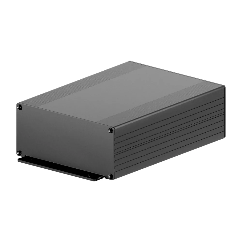
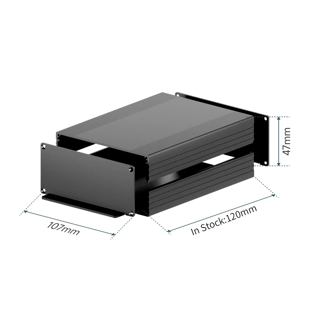
Oh, and by the way, the dimensions of the enclosure are 4" x 4.75" x 1.85", and the end caps have integrated mounting tabs for surface mounting if you like. I anticipate this unit will simply replace the factory amp, which is much larger than this is, so it can probably be secured into place inside the kick panel with zip ties, but the tabs are available to anyone who prefers to fabricate a custom bracket for a pro-level install.
Let me know any questions you may have. Talking through stuff gives me more to think about and helps me catch issues I hadn't considered. I appreciate your enthusiasm about this project! It's a ton of work but it's also extremely satisfying and fun.
Now for some pics - the enclosure, and the daughterboard. For the daughterboard, one of the OEM amp's connectors is so new that the manufacturer has not yet released a 3D step file for it, so it is missing from the 3D render pasted below. I've emailed them asking if they can send one - we'll see!


Here's a sort of list of evolutions that have happened, in order, which should hopefully give some context to the progression:
- I moved away from using an Arduino microcontroller, to instead building my own microprocessor network. Reasons for this change were: automotive-grade reliability, as the Arduino isn't designed to operate permanently in an automotive environment, which sees wild temperature and humidity ranges that a "home" device isn't designed for. Moving to "bare metal" allowed me to pick high temperature range components all the way down to resistors and capacitors. The second thing I'll be able to do in the name of reliability is to apply a conformal coating to the whole device, which is another automotive manufacturer-grade manufacturing step that prevents corrosion over time, as it creates a hermetic seal over every surface. The final reason to do this is to get back some board real estate, which I knew I was going to need for the next idea I had...
- ...which was to bring onboard the entire "T" harness assembly into the device. I won't bore you with the details, and just say this took the most time to do. This strategic change makes the device truly drop-in. On one side of the device you will have the three exact same connectors that your factory amplifier has, arranged in the exact same order and orientation. On the opposite end of the device you'll have the SPDIF output, and a custom harness that I'll supply, which contains all of the cabling to run to your DSP, all in one bundle. Speaker wires, remote turn on, and the volume control all in one neat package. You're just running that one harness and a digital coaxial cable to your DSP amp. That's it.
- Finally, in order to enable (2) and not have a massive footprint, I realized I needed to split the platform into a motherboard and daughterboard, which would sandwich on top of each other in a clamshell enclosure (see below for a manufacturer photo of the exact enclosure I will use). There will be a simple internal bridge connector between the two boards for them to talk to each other. There's a hidden benefit to this change that might actually be the most powerful of all so far: The motherboard contains all the logic for the volume control while the daughterboard houses all the power, I/O and passthrough signals, and consequently all the vehicle harness connectors too. Why does this matter? Well, I've learned that current gen Honda/Acuras do not all share the same pinouts across models. Even the Civic with Bose is slightly different from my Acura with ELS. So, to add new cars, I only need to develop a new daughterboard, which is much less complex than rearranging the logic circuitry just because the I/O has changed.
Oh, and by the way, the dimensions of the enclosure are 4" x 4.75" x 1.85", and the end caps have integrated mounting tabs for surface mounting if you like. I anticipate this unit will simply replace the factory amp, which is much larger than this is, so it can probably be secured into place inside the kick panel with zip ties, but the tabs are available to anyone who prefers to fabricate a custom bracket for a pro-level install.
Let me know any questions you may have. Talking through stuff gives me more to think about and helps me catch issues I hadn't considered. I appreciate your enthusiasm about this project! It's a ton of work but it's also extremely satisfying and fun.
Now for some pics - the enclosure, and the daughterboard. For the daughterboard, one of the OEM amp's connectors is so new that the manufacturer has not yet released a 3D step file for it, so it is missing from the 3D render pasted below. I've emailed them asking if they can send one - we'll see!
Last edited:
OP
OP
ashmostro
Senior Member
- Thread starter
- #94
Someone asked an excellent question on another forum, that I should have addressed above:
The one caveat which is a higher risk is if the DSP only uses a digital controller with no analog volume control circuitry at all. My device is not able to transcode such a communication strategy. That said, so far I have not found an amp that does not have an analog control option, if it has external volume control ability. But the possibility is always there.
Now, for the hopefully more satisfying answer: I fully intend to test amplifiers via volunteer, to "certify" which brands and models are compatible, and will publish that information with the device. So far, it looks like Helix is going to be the second brand that is certified to work (Arc Audio is proven to be compatible already as that's what I have).
When the product is shippable I'll poll the enthusiast community to find out which brands are the most popular within the interested pool of users. That will inform what I work to certify next.
So, the short version is, any DSP/amp that offers or includes an accessory remote control knob is likely to be compatible, with one caveat. Most DSP volume controls on the market are actually relatively simple circuits: a three-wire potentiometer, supplied by 3.3V or 5V from the amp. Any amp that uses this topology is highly likely to be compatible. The only risk (and it's very very minor) is if the amp has sophisticated sensing technology built into that circuit that would disable external volume control ability unless the expected values are sensed. I say this risk is very minor as I have yet to see an amp that does this - most just do what you tell them in the software (ie you tell it "volume controller is present" through a checkbox in the software).So what features should one look for in a DSP in order to utilize your device? Can it be done with the plethora of $100 DSP devices on Amazon, or does it need certain features only found on X, Y, Z brands? I can appreciate a good rabbit hole, and this is about as rabbit hole as it gets.
The one caveat which is a higher risk is if the DSP only uses a digital controller with no analog volume control circuitry at all. My device is not able to transcode such a communication strategy. That said, so far I have not found an amp that does not have an analog control option, if it has external volume control ability. But the possibility is always there.
Now, for the hopefully more satisfying answer: I fully intend to test amplifiers via volunteer, to "certify" which brands and models are compatible, and will publish that information with the device. So far, it looks like Helix is going to be the second brand that is certified to work (Arc Audio is proven to be compatible already as that's what I have).
When the product is shippable I'll poll the enthusiast community to find out which brands are the most popular within the interested pool of users. That will inform what I work to certify next.
Spart
Senior Member
I do wonder how much is truly different. Ford does something similar with their harnesses, and it'll be 98% the same but for a few pins.The motherboard contains all the logic for the volume control while the daughterboard houses all the power, I/O and passthrough signals, and consequently all the vehicle harness connectors too. Why does this matter? Well, I've learned that current gen Honda/Acuras do not all share the same pinouts across models. Even the Civic with Bose is slightly different from my Acura with ELS. So, to add new cars, I only need to develop a new daughterboard, which is much less complex than rearranging the logic circuitry just because the I/O has changed.
If they're overwhelmingly similar, it might be a good idea to explore a configurable board with jumpers or DIP switches. But you'd have to know what the differences are, first.
Sponsored
acurax
Senior Member
I do wonder if the daughter board approach results in any hot spots which may be problematic or are you using the encloser as a means of managing heat build-up.
Someone w/ 3D modeling skills could probably design some mounts, vs zip ties, that could be 3D printed for those who prefer a more pro-level install.
Someone w/ 3D modeling skills could probably design some mounts, vs zip ties, that could be 3D printed for those who prefer a more pro-level install.
OP
OP
ashmostro
Senior Member
- Thread starter
- #98
This could work, but it would likely actually create more circuit complexity and insertion loss, as well as being net-net more effort to engineer than to manage independent boards for each model, which can subsequently be trace-length optimized for each application. Further, the moment you have a different connector type to deal with, the board won't be applicable. Better to go modular for these reasons.If they're overwhelmingly similar, it might be a good idea to explore a configurable board with jumpers or DIP switches. But you'd have to know what the differences are, first.
Spart
Senior Member
Yeah it really depends on what wires they're moving around, and the connector staying the same.This could work, but it would likely actually create more circuit complexity and insertion loss, as well as being net-net more effort to engineer than to manage independent boards for each model, which can subsequently be trace-length optimized for each application. Further, the moment you have a different connector type to deal with, the board won't be applicable. Better to go modular for these reasons.
OP
OP
ashmostro
Senior Member
- Thread starter
- #100
I fully anticipate someone will do this and share it with the community! I am focused on getting a working drop-in product to market first, and then if there's time I can tackle this (but I suspect someone will get to it before me!)Someone w/ 3D modeling skills could probably design some mounts, vs zip ties, that could be 3D printed for those who prefer a more pro-level install.
Sponsored
acurax
Senior Member
I have the right hardware and software, but I'm far from skilled at designing things in Blender. Also, not having the measurements for where the amp mounts or the measurements for the mounting points on your case it pretty much precludes me from even attempting to make something.I fully anticipate someone will do this and share it with the community! I am focused on getting a working drop-in product to market first, and then if there's time I can tackle this (but I suspect someone will get to it before me!)
Victorofhavoc
Senior Member
- First Name
- Gordan
- Joined
- Jul 9, 2024
- Threads
- 12
- Messages
- 1,506
- Reaction score
- 1,039
- Location
- Kansas City
- Car(s)
- Integra type s
Have you played with Claude for filling that blender skill gap? I was in the same situation, and for a specific project Claude got me over the skill and knowledge gaps quite a bit faster, as well as making about 90% of the base image I used.I have the right hardware and software, but I'm far from skilled at designing things in Blender. Also, not having the measurements for where the amp mounts or the measurements for the mounting points on your case it pretty much precludes me from even attempting to make something.
OP
OP
ashmostro
Senior Member
- Thread starter
- #104
Exciting Update 3/31/26:
PCB orders have been placed for the motherboard and both vehicle model daughterboards (Honda Civic XI with Bose, and Acura Integra DE4/DE5 with ELS)!
There was a lot of fiddly stuff to address in the design in order to get a clean and reasonably-priced build. All SMD devices will be placed by the PCB manufacturer and I'll be soldering the through-hole components because that's pretty easy, so no need to pay for that. I'll be looking for two beta testers per model, but I won't be doing that until I've tested this in my own car first so I don't waste anyone's time if there's a surprise bug in the design. It also gives me time to measure the specs for the end cap cutouts (for the connectors), and I'll probably be fabricating an adapter mount that allows you to bolt this device to the factory mount that hold the OE amplifier (which you'd be removing from the car).
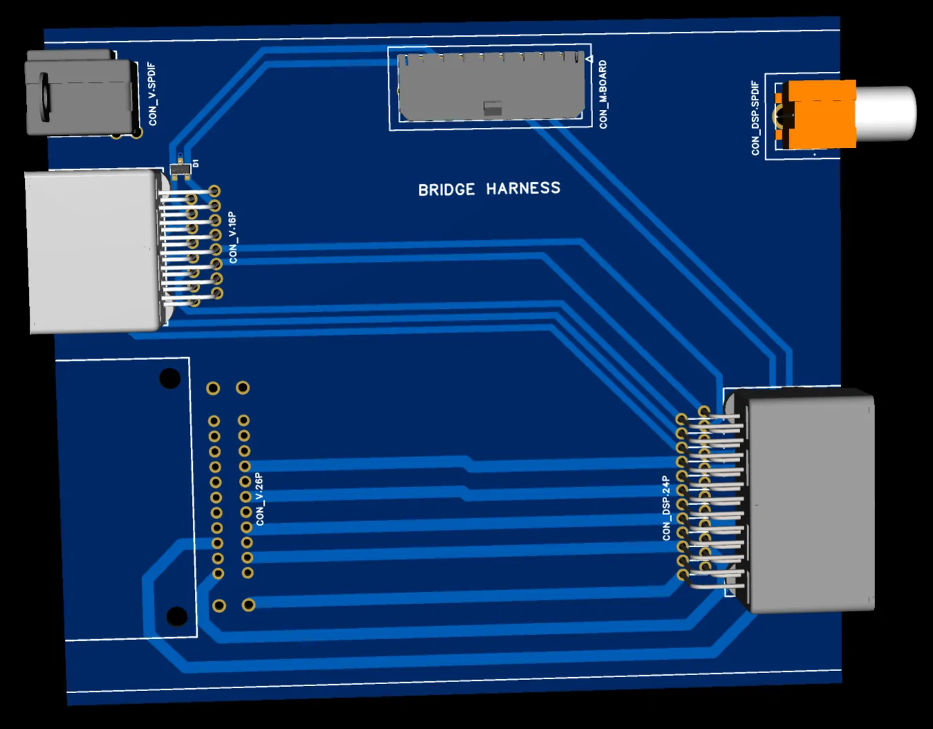
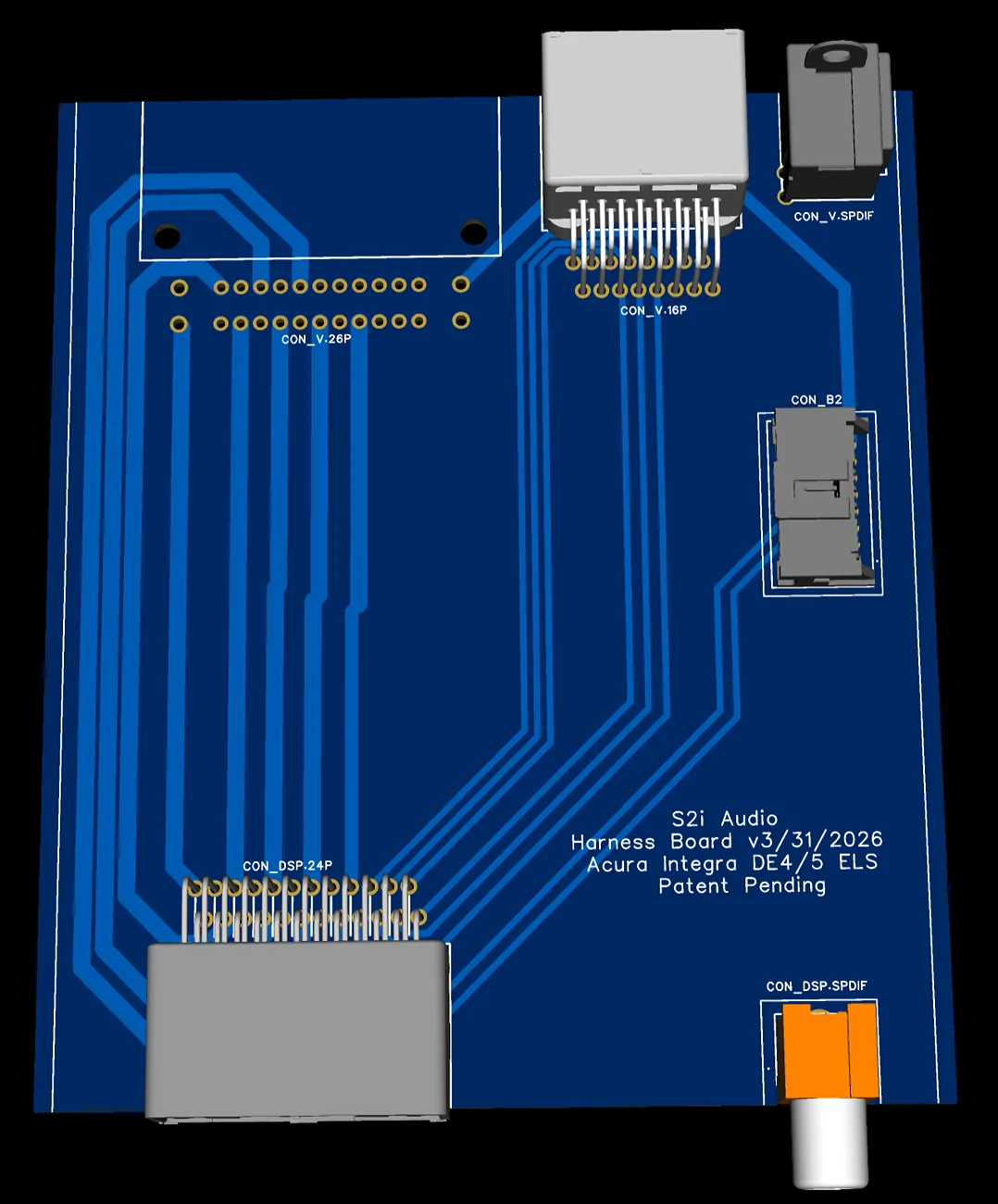
Including some glamour renders for giggles. On the daughterboards, there's one connector missing from the render because there's still no 3D model from the manufacturer, so you'll just have to imagine it's the factory 26-pin connector from the OE amplifier :ROFLMAO:
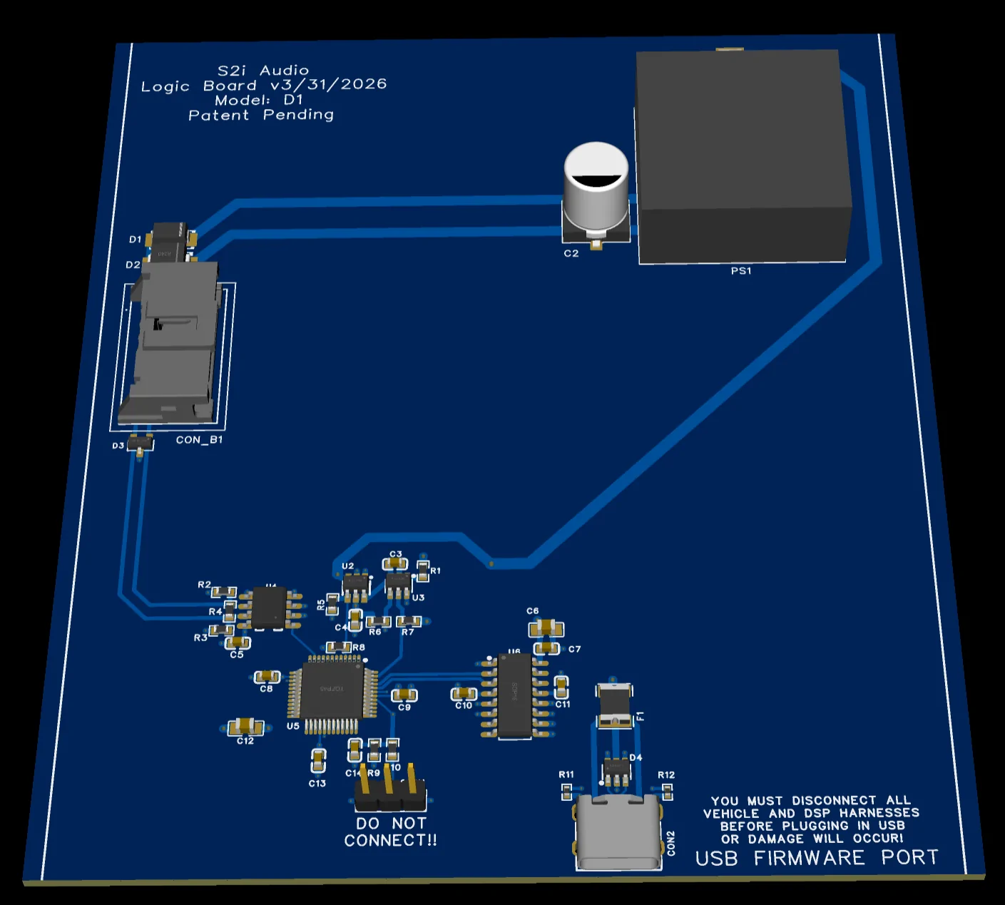
Logic Board (likely will be a standard part for all late model Honda/Acura cars):

Integra-specific daughterboard. Notice it only has connectors and no solid-state devices. This keeps the cost of adding new models down, and even allows the end user to side-grade to a different model if they change cars (to another supported vehicle). You'd just need a new daughterboard and a new harness if the pinouts differ.

And the Honda Civic model. Note how the traces are markedly different. This is because of the different pinouts on the OE 26 pin connector at the upper left (the missing one, lol)

Note "CON_B1" and "CON_B2" in the two boards - that is where there will be a bridge connector between the two boards. All connectors and devices are automotive grade for longevity and reliability.
Thanks to all those who have continued to show interest in this project. It's been a lot of work (and cost) but you've really helped keep up my motivation to get this done quickly. And yes, you will notice that there is now a "Patent Pending" on the device. This started out as a need I was trying to fill for myself alone, then I realized I had something other enthusiasts might be able to reproduce, and then it evolved into a full-fledge drop-in part that almost anyone (and definitely any competent installer) can implement in their system. I now plan on selling this product at whatever scale the interest level ends up being, and if it's really popular I'll invest more R&D into support more models of cars and doing testing on DSPs to "certify" which ones will work the best with the Integrator.
I'll let y'all know when I'm ready for those Beta Testers! Will want to know your system configurations first, and I'll select the ones most appropriate for the test. It will be two Honda Civics and two Acura Integras initially.
Thanks all,
-Ash
PCB orders have been placed for the motherboard and both vehicle model daughterboards (Honda Civic XI with Bose, and Acura Integra DE4/DE5 with ELS)!
There was a lot of fiddly stuff to address in the design in order to get a clean and reasonably-priced build. All SMD devices will be placed by the PCB manufacturer and I'll be soldering the through-hole components because that's pretty easy, so no need to pay for that. I'll be looking for two beta testers per model, but I won't be doing that until I've tested this in my own car first so I don't waste anyone's time if there's a surprise bug in the design. It also gives me time to measure the specs for the end cap cutouts (for the connectors), and I'll probably be fabricating an adapter mount that allows you to bolt this device to the factory mount that hold the OE amplifier (which you'd be removing from the car).
Including some glamour renders for giggles. On the daughterboards, there's one connector missing from the render because there's still no 3D model from the manufacturer, so you'll just have to imagine it's the factory 26-pin connector from the OE amplifier :ROFLMAO:
Logic Board (likely will be a standard part for all late model Honda/Acura cars):
Integra-specific daughterboard. Notice it only has connectors and no solid-state devices. This keeps the cost of adding new models down, and even allows the end user to side-grade to a different model if they change cars (to another supported vehicle). You'd just need a new daughterboard and a new harness if the pinouts differ.
And the Honda Civic model. Note how the traces are markedly different. This is because of the different pinouts on the OE 26 pin connector at the upper left (the missing one, lol)
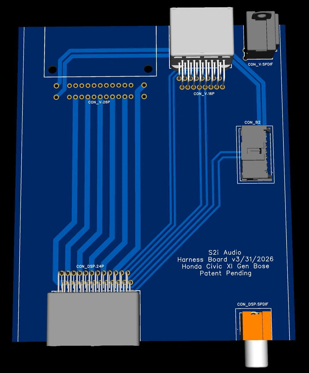
Note "CON_B1" and "CON_B2" in the two boards - that is where there will be a bridge connector between the two boards. All connectors and devices are automotive grade for longevity and reliability.
Thanks to all those who have continued to show interest in this project. It's been a lot of work (and cost) but you've really helped keep up my motivation to get this done quickly. And yes, you will notice that there is now a "Patent Pending" on the device. This started out as a need I was trying to fill for myself alone, then I realized I had something other enthusiasts might be able to reproduce, and then it evolved into a full-fledge drop-in part that almost anyone (and definitely any competent installer) can implement in their system. I now plan on selling this product at whatever scale the interest level ends up being, and if it's really popular I'll invest more R&D into support more models of cars and doing testing on DSPs to "certify" which ones will work the best with the Integrator.
I'll let y'all know when I'm ready for those Beta Testers! Will want to know your system configurations first, and I'll select the ones most appropriate for the test. It will be two Honda Civics and two Acura Integras initially.
Thanks all,
-Ash
Sponsored